Design Considerations for the Meshing of Pinion and Slewing Bearings
— On the Importance of Tooth Count, Tooth Surface Hardening, and Tooth Profile Modification
In the slewing bearing drive system, the meshing quality between the pinion and the internal or external gear ring of the slewing bearing directly determines the load-bearing capacity, service life, and operational reliability of the entire slewing system.
In practical engineering applications, if the pinion design is not properly executed, issues such as root weakening, premature wear, tooth breakage, or even the failure of the entire slewing system can easily occur.
Among these, an insufficient number of teeth, lack of tooth profile modification, and absence of tooth surface hardening are the three core factors leading to failure. The following provides a systematic explanation of this issue from the perspectives of processing methods, meshing principles, and engineering practice.
- Common Processing Methods for Pinions and Their Limitations
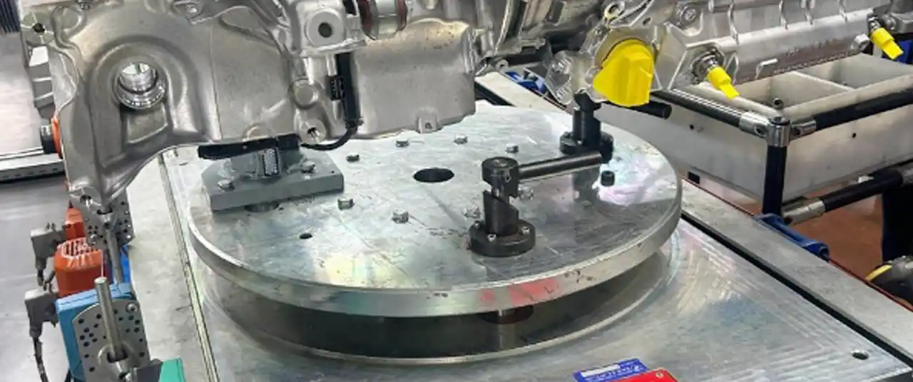
Currently, one of the most widely used processing methods for pinions is hobbing.
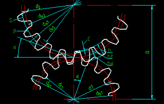
Hobbing belongs to the generating method, which means that the involute tooth profile is formed by simulating the gear meshing process through the relative motion between the hob and the workpiece.
During the hobbing process, the tooth profile is not formed in a single step but is gradually generated by the “imaginary rack” through incremental cutting.
This processing method offers high efficiency and stable precision, making it highly suitable for medium to large-scale production. Consequently, it is widely adopted for manufacturing pinions that are matched with slewing bearings.
However, when the number of gear teeth is small, hobbing inevitably introduces a serious issue—undercutting.
What is Undercutting? Why is it More Likely to Occur with Fewer Teeth?
1.Definition of Undercutting
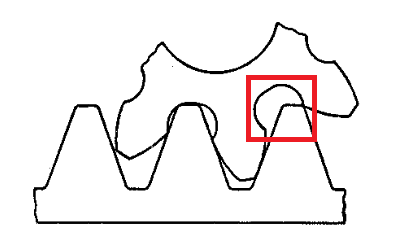
Undercutting refers to the phenomenon during gear processing where, due to an insufficient number of teeth, the hob intrudes into the root area of the tooth while cutting the tooth profile. This removes material from the root that should have been retained, resulting in a thinning of the root section.
From a geometric perspective, undercutting disrupts the continuity of the involute tooth profile at the root.
From a mechanical perspective, undercutting significantly reduces the bending strength of the tooth root.
2.Why is Undercutting Prone to Occur with Tooth Count ≤ 17?
In the standard gear system (20° pressure angle, standard addendum coefficient), there is a recognized critical value:
For standard spur gears, when the tooth count is ≤ 17, undercutting is inevitable during hobbing.
This is determined by the geometric characteristics of the involute profile, not by machining errors.
When the number of teeth is too small:
- The base circle diameter decreases.
- The starting point of the involute curve moves closer to the tooth root.
- The cutting path of the hob inevitably intrudes into the root area.
Even with the highest machining accuracy, the phenomenon of undercutting cannot be avoided.
III. Practical Hazards of Undercutting in Slewing Bearing Systems
In ordinary transmission gears, slight undercutting might be acceptable.
However, in slewing bearing drive systems, undercutting constitutes a high-risk design flaw for the following reasons:
- Significant Reduction in Tooth Root Strength
Slewing bearings operate under conditions involving:
- Large module
- High torque
- Low speed and heavy load
- Shock loads and frequent starts/stops
The tooth root is the area subjected to the highest bending stress. Once weakened by undercutting, it is highly susceptible to:
- Fatigue cracks at the tooth root
- Crack propagation
- Eventual tooth breakage
- Increased Meshing Impact
Undercutting leads to an incomplete tooth profile, causing:
- Shortening of the actual line of action
- Non-uniform meshing stiffness
During slewing start-up or reversal, shock loads concentrate on the weakened root area, further amplifying the risk of failure.
- Drastic Reduction in the Service Life of the Entire Slewing System
Once tooth root fracture occurs in the pinion:
- It quickly damages the slewing bearing gear ring.
- Metal debris enters the interior of the slewing bearing.
- This leads to irreversible secondary damage.
Such failures in construction machinery often mean the scrapping of the entire slewing system.
- Why Must the Pinion Tooth Count Exceed 17?
Based on the above mechanisms, we explicitly state for slewing bearing applications:
The pinion tooth count should be greater than 17. This is the basic prerequisite for avoiding undercutting.
When the number of teeth increases:
- The starting point of the involute curve moves away from the root.
- The hob no longer intrudes into the dangerous area.
- The tooth root profile remains intact.
- Bending strength is significantly improved.
In engineering practice, the common safe design range is:
- 18–25 teeth (for small to medium modules)
- For larger modules, specific load verification is required.
Why is Tooth Profile Modification Also Essential?
Even if the tooth count exceeds 17, merely “avoiding undercutting” is still insufficient for slewing bearing applications.
- The Role of Tooth Profile Modification
Tooth profile modification (Profile Shift) refers to intentionally adjusting the position of the hob relative to the gear’s pitch circle during hobbing, thereby altering the tooth profile distribution.
Positive profile shift can provide:
- Thickened tooth root
- Increased root fillet radius
- Significantly reduced stress concentration at the tooth root
This is particularly important for low-speed, heavy-duty, long-life applications like slewing bearings.
- Special Characteristics of Slewing Bearing Systems
Unlike ordinary high-speed gears, slewing bearing drives feature:
- Low meshing speed
- Long single-tooth load duration
- Obvious superposition of contact stress and bending stress
Through positive profile shift, one can:
- Optimize the tooth root strength distribution
- Increase the safety factor
- Extend fatigue life
Therefore, in the design of components matched with slewing bearings, applying reasonable positive profile shift to the pinion is virtually an industry consensus.
- Why Must the Pinion Undergo Tooth Surface Hardening?
- The Slewing Bearing Gear Ring is Typically Surface-Hardened
Whether for internal or external gear slewing bearings, their gear rings usually undergo:
- Induction hardening
- Or overall quenching and tempering + surface hardening
The tooth surface hardness is generally high.
- What Happens if the Pinion is Not Hardened?
If the pinion tooth surface hardness is significantly lower than that of the slewing bearing gear ring:
- Biased wear occurs during the initial meshing phase.
- The pinion becomes the “sacrificial component.”
- The tooth profile degrades rapidly.
- Meshing impact further intensifies.
This ultimately leads to:
- Premature failure of the pinion.
- Abnormal wear on the gear ring.
- The Core Purpose of Tooth Surface Hardening
Performing tooth surface hardening on the pinion achieves:
- Improved wear resistance.
- Ensured hardness compatibility for meshing.
- Reduced risk of pitting and scuffing.
- Extended service life of the entire slewing system.