When equipment starts making unusual noises or even seizes up suddenly, experienced engineers will first check a parameter often overlooked by others.
A slewing bearing in operation begins emitting a sharp, screeching noise, followed by an unsettling grinding sound, ultimately leading to a complete lock-up of the equipment—such failures are regrettably common on many work sites. While most maintenance personnel immediately check lubrication, bearing raceways, or mounting bolts, they often miss the root cause: improper gear backlash design.
A widely misapplied rule-of-thumb formula, “0.2 × Module,” is silently damaging the drive systems of countless heavy-duty machines.
01 The Misleading Rule of Thumb: Why “0.2 × Module” Fails as a Design Standard
Within the slewing bearing industry, the relationship between gear backlash and module is often simplified to a seemingly handy mnemonic: backlash equals 0.2 multiplied by the module. For instance, a gear with module 10 automatically gets a backlash setting of 2mm.
While this simplification might be useful for initial estimations, it is risky as a design standard. In reality, the reasonable range for gear backlash should vary between (0.04 ~ 0.3) × Module, with 0.2 × Module being merely the midpoint value within this range, not a universal solution.
The Key Misconception: This empirical value is often mistakenly used as the recommended minimum backlash, overlooking real-world conditions like thermal expansion under high temperatures and deformation under heavy loads. When actual operating conditions exceed the assumptions, this supposed “safety value” becomes the trigger for seizure.
02 Standard Analysis: The Scientific Basis and Key Factors in Backlash Design
According to the Chinese National Standard GB/T 10095.2-2008 and the industry standard JB/T 2300-2018, gear backlash is directly determined by the amount of tooth thinning. The allowable range for this thinning is based on a comprehensive consideration of module, pitch diameter, and accuracy grade.
The backlash calculation formula is: X ≈ 2 × |ΔE_{sns}| × sinα_n
Here, ΔE_{sns} is the total tooth thickness reduction, and α_n is the normal pressure angle. This formula clearly shows that backlash is determined by the allocation of design tolerances, not a simple multiplication.
Six Key Factors Affecting Slewing Bearing Backlash:
- Temperature Effects: Under direct sunlight, a slewing bearing’s surface temperature can exceed 60°C, while its internal temperature might only be 30°C. With 25°C temperature difference is enough to cause over 1mm of thermal expansion in a 2-meter diameter gear ring, completely negating the theoretical backlash.
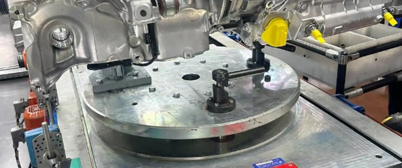
- Load Deformation: Under full load, as with an excavator, the thin-walled structure of a slewing bearing experiences elastic deformation. Notably, the gear ring can become elliptical, causing local backlash to decrease sharply.
- Accuracy Grade: Slewing bearings typically use accuracy grades 7-9. Their tooth thickness and center distance tolerances are larger than those for precision machine tool gears, requiring a greater backlash allowance.
- Lubrication Requirements: Oil spray lubrication requires greater backlash than grease lubrication to ensure proper oil film formation.
- Installation Errors: On-site errors in center distance directly affect the final backlash.
- Application Differences: Wind power equipment, prioritizing smooth transmission, can have smaller backlash. Mining machinery, impact loads, requires larger backlash.
03 Industry Practice: The Backlash Design Philosophy of Luoyang and Xuzhou Enterprises
In China’s two major slewing bearing industrial hubs, companies approach backlash design with different technical traditions, reflecting their unique contexts.
Slewing bearing enterprises in Luoyang, such as Xinqianglian and LYC Bearing, leverage the technical heritage of this established industrial base. They typically perform personalized calculations strictly according to national standards. These companies will inquire in detail about customer operating parameters and may even dispatch engineers to conduct on-site measurements of ambient temperature and load profiles.
The slewing bearing industry cluster in Xuzhou has inherited advanced production techniques and developed its own unique technological ecosystem. The local supporting processing plants, through long-term service to OEMs, have accumulated rich field data feedback. They understand how to adjust backlash for specific environments, such as the summer heat in Xuzhourotherde or the dusty conditions of Shanxi coal mines.
Industry Observation: Luoyang-based companies tend to offer more standardized backlash solutions, while Xuzhou’s supporting plants excel in rapid customization and adjustment. This distinction stems from the different industrial structures and customer bases of the two regions.
04 Design in Practice: How to Scientifically Determine Slewing Bearing Gear Backlash
Correct backlash design should start with empirical formulas but must never end there. The following outlines a scientific design process:
Step 1: Basic Calculation
Begin with 0.2 × Module as a starting point. Determine the tooth thickness tolerance range by consulting the standard based on the accuracy grade. For a slewing bearing with module 12, pitch diameter 1500mm, and accuracy grade 8, the upper deviation (Ess) of tooth thickness is typically between -0.25mm and -0.40mm.
Step 2: Operating Condition Modification
Evaluate the equipment’s working environment:
– Daily temperature swing exceeds 30°C? Add a backlash allowance of 0.1 × Module.
– Subject to impact loads? Add another 0.05 × Module.
– Continuous operation over 8 hours? Consider thermal accumulation effects.
– High-altitude or extremely cold environments? Special calculation for material shrinkage rate is required.
Step 3: Application-Specific Adjustment
Backlash requirements vary drastically for different equipment:
– Wind Turbine Pitch Bearings: Prioritize smooth transmission. Backlash: (0.06 ~ 0.15) × Module.
– Excavator Slewing Bearings: Withstand significant impact. Backlash: (0.2 ~ 0.3) × Module.
– Radar Pedestal Bearings: Require high positioning accuracy. Backlash: (0.04 ~ 0.1) × Module.
– Port Crane Bearings: Balance smoothness and durability. Backlash: (0.1 ~ 0.25) × Module.
Step 4: Verification and Feedback
After manufacturing the first article, conduct a full-load thermal run-in test. Measure the actual backlash variation under different conditions and adjust design parameters accordingly. Ideally, the minimum backlash under the most severe operating conditions should not be less than 0.05 × Module to avoid gear interference.
5 Fault Diagnosis: Steps to Take When Backlash Issues Occur
If equipment is already experiencing noise or sticking due to improper backlash, follow these diagnostic steps:
- Sound Analysis: A uniform “humming” sound may indicate insufficient backlash; an irregular “clicking” or “clacking” sound could point to excessive backlash causing impact.
- Temperature Monitoring: Use an infrared thermometer to measure the temperature at the gear mesh point. A temperature 15°C or more above ambient suggests severe friction, potentially due to insufficient backlash.
- Contact Pattern Check: Apply Prussian blue to the tooth surface. After slow rotation, inspect the contact pattern. A pattern close the tooth tip or root indicates abnormal meshing.
- On-site Measurement: Use a feeler gauge to measure backlash at multiple points. A variation exceeding 30% around the same circumference indicates significant gear ring deformation.
For backlash issues with products already in the field, maintenance service providers in Luoyang and on-site repair teams in Xuzhou offer different strengths: the former excel in systematic redesign and replacement, while the latter are proficient in on-site adjustment and emergency handling.
06 Technology Frontiers and Real-World Cases
With advancements in measurement technology, “Laser Backlash Detectors” can now monitor backlash changes in large slewing bearings online with an accuracy of 0.01 mm. At a wind farm in Hebei, engineers discovered through real-time data that backlash decreased by 68% when temperature rose from -20°C to 30°C. This finding prevented large-scale gear damage.
At a port in Jiangsu, a gantry crane developed severe noise after only three months of operation due to a slewing bearing with incorrect backlash parameters. The repair team found the actual backlash was only 40% of the design value. The root cause was the design’s failure to account for increased friction coefficient due to salt spray corrosion in the coastal environment.
Core Insight: The essence of gear transmission is precise motion control, and backlash is the variable buffer zone within that control—too small leads to rigid system impacts, too large results in loss of control precision. In a field where even micron-level errors can be magnified, no empirical formula should replace rigorous systems engineering calculations.